
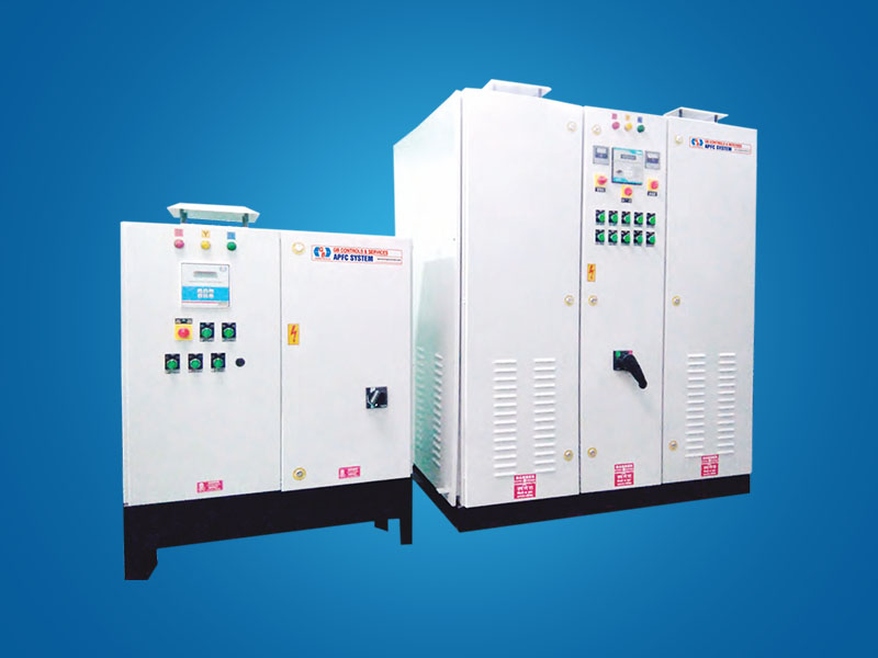

Thyristor/Contactor Switched APFC System
LT APFC SYSTEM Reactive Power compensation system is designed to work automatically on LT power supply to measure, display & connect/ disconnect the required capacitor banks through Thyristor with protection of MCB / HRC Fuses & series reactors(0.4% OR 7.0%) to each bank, to achieve the set Target power factor. Thyristor Switched Automatic power factor system is the highly accurate, properly designed system with required creep age distances as per required standards. APFC System equipped with advanced, digital Microprocessor based Relay to measure, calculate and display all electrical network parameters. It accurately measures cycle to cycle Reactive Power requirement for set target power factor & initiate command to Switching element /device installed in the system, so as required capacitors are connected /disconnected to the network. APFC controllers close loop fast response multi method switching [MMS] algorithm that helps system to have close & precise control on power factor. APFC Relay has memory storage model of capacity 45 Days on hourly basis with RS 232 port for communication. Separate module is available with one year storage capacity with adding SD card and interfacing facility.
Features:
- Modular Structure
- Protection To Each Step
- Powder Coated Metallic Frame Structure Design
- Well Ventilated Design
- Four Modes Of Operation
- Door Interlocks
GB Controls APFC Systems Applications Use For:
- Automobile Industries
- Pharmaceutical Industries
- Windmill, Power Stations
- Cement Industries, Metal Industries
- Hospitals, Malls, Banks, IT Parks
- DG stations, Crushers
- Chemical & Fertilizer Plant
- Commercial Complexes
- Railway / MES etc
|
STANDARD TECHNICAL SPECIFICATION |
|
|
Rated Voltage |
440V/3 PHASE/50Hz. |
|
Operating Voltage |
110/230/440V/3 PHASE/50Hz. |
|
Current Input |
IN/5 Amp. Or IN/1 Amp |
|
APFC Relay |
4/8/12/16 Stage Apfc relay with bank ON / Off LED Indication with measurement & calculation all Electrical parameters |
|
Switching Element |
Thyristors Modules. (Thyristor Switch ON through Zero Crossing Firing Card) |
|
Protections |
MCB/MCCB/HRC FUSES /Series reactors to each banks |
|
Operating modes |
MCB/MCCB/HRC FUSES /Series reactors to each banks |
|
Interface |
RS-232/RS-485/GSM (Optional) |
|
Steps Outputs |
Maximum 16 steps |
|
Cabinet |
Free stand floor mounting frame structure Metal cabinet suits to Indoor/Outdoor |
Display Parameters of APFC Relay:
Voltage, Current, Power Factor, Active Power (KW), Apparent Power (KVA) - all at LT SIDE, Reactive Power (KVAR), Capacitive Reactive Power (KVAR), Active Energy (KWH), Apparent Energy (KVAH), Reactive Energy (KVARH), Real Time, Date, Network Fault Message Display, Capacitor Bank Status Display, Load Side Parameters (viz. Current, P.F. & KVA).
Protections:
Controller offers protections in the following situations : High Voltage, Low Voltage, Over-Load, Under-Load, Voltage Imbalance, Load Current Imbalance, Over Capacitor Current, Capacitor Current, Imbalance, Over Temperature etc.
|
PROGRAMMABLE PARAMETERS OF APFC RELAY |
|
|
Target Power Factor |
0.90 lead to 0.85 lag |
|
Time Delay (Td) |
In Seconds/in milliseconds to seconds |
|
Capacitor's discharge time |
In milliseconds to seconds |
|
CT Ratio |
Primary and secondary Current Transformer ratio to measure actual load |
|
PT Ratio |
Potential Transformer ratio to measure actual voltage |
|
No. of Steps |
1 to 16 Capacitor steps |
|
Capacitor Step Rating |
1kvar to 1000 kvar |
|
Compensation mode |
fine-Average/Minimum/Maximum of load KVAR basis |
Power Factor Correction:

Hence Power Factor can never be greater than 1.00
Power Factor at best can be equal to 1.00
Usually P.F is always Lag (Inductive): This is because in any industry, the majorities of the Loads (for e.g. Induction Motors, etc.) are Inductive in nature and consume reactive power to meet their magnetic field requirements. Some times P.F can be ?Lead? (Capacitive): This situation normally arises when there are excessive Capacitors in the installation compared to actual kvar requirement of the Inductive Loads in the installation. Industries use large number of AC motors, DC Drive, Rectifier, Compressors, Induction Furnaces and Welding Machines resulting in lower Power Factor. In Such Industries, Reactive Power varies rapidly within every few cycles. Such uncompensated Reactive Power leads to poor P.F Voltage Instability, Flickering, High Current consummation increase in Maximum Demand, High Losses, Low Electric Supply Loading Capacity & Over Heating of Switchgear and Cables, High Wear & tear of Switchgears and Cables. Low Power Factor results in to heavy penalties. The equipment for Power Factor improvement serves the purpose to relive the electrical supply of inductively operating consumer by the reactive current & thus saves operational cost. The conventional systems are not suitable for compensating rapid variable reactive power demand.
Why Power Factor is Important? Low Power Factor means:
- Inefficient use of Electrical Energy
- Overloading of Cable, Switchgear and Bus Bar
- Imposes larger kVA demand
- Reduced revenue to Electrical Utilities
- Overloading of Transformer/Generator
- Higher temperature due to increased losses
- Limits No. of loads that can be connected
- Poor Voltage Regulation
Why improve Power Factor?
- Avoid Power Factor Penalties
- Reduction in Line Losses
- Reduction in kVA Demand
- More revenue to Utilities
- Reduction in current drawn
- Enables more load to be connected
- Increased life of Electrical Equipment
- Improved Voltage Regulation
What is the Power Factor of various loads?
- Resistive Heaters - 1.00
- Induction Motors - 0.7 to 0.85 Lag
- Computers - < 0.9 lead
- Induction Furnace - 0.7 to 0.8 Lag